
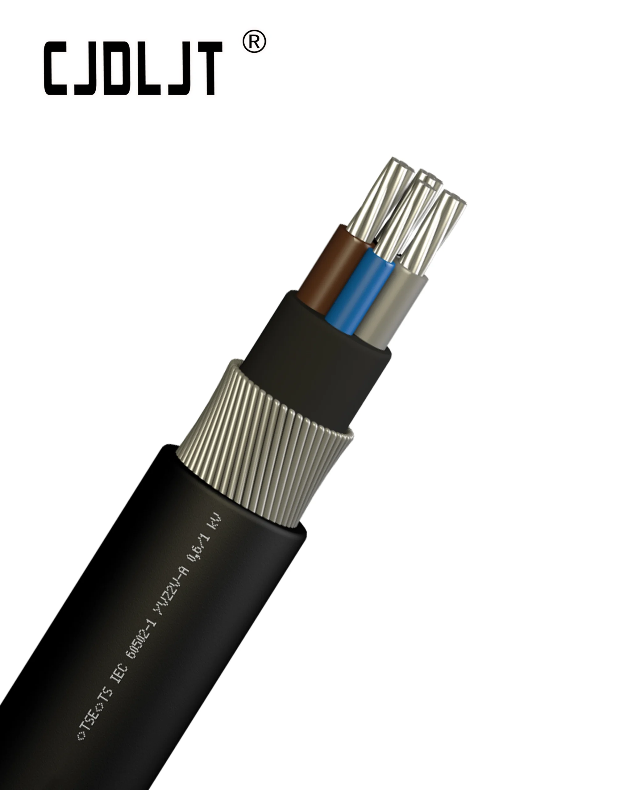


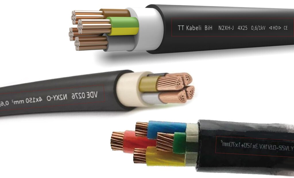
The alphanumeric codes printed on cable jackets are not arbitrary markings. They represent a highly standardized coding system that defines a cable’s physical structure, material composition, rated performance, and application suitability. Whether referencing global standards such as IEC 60502, Germany’s VDE 0276, or national GB standards, the underlying nomenclature logic remains consistent. Understanding this structural sequence—moving from special performance characteristics to insulation, conductor type, shielding, armor, and outer sheathing—is essential for precise engineering selection and avoiding costly procurement errors.
Conductor Material and Core Configurations
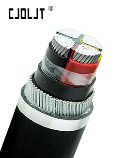
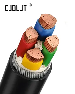
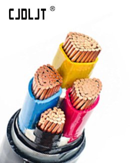
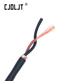
This segment identifies the conductor material and core specifications, which establish the cable’s current-carrying capacity and primary application baseline.
Conductor Material (Letter Designations): Copper: When no material letter is specified in the prefix, the conductor defaults to copper, which is favored for its superior conductivity and electrical stability.
Aluminum: Utilized as a lightweight, cost-effective alternative. Its designation varies by regulatory standard: in GB standards, “L” denotes an aluminum conductor (e.g., YJLV) ; in VDE standards, the letter “A” is prefixed to the model code (e.g., ANYY) ; whereas IEC standards typically specify this via a descriptive suffix (e.g., Class 2 Aluminium Conductor) rather than a prefix code.
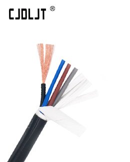
Core Specifications (Numerical Layout): Formatted as “Number of Cores × Cross-Sectional Area”. Common configurations include:
- 1 × 2.5 / 1 × 4: Single-core cables utilized for low-load branch circuits like domestic lighting.
- 2 × 2.5 + 1 × 1.5: Two phase conductors and one grounding conductor, designed for single-phase equipment such as air conditioning units.
- 3 × 50 + 1 × 25: Three phase conductors and one grounding conductor, engineered for industrial machinery and primary distribution boards.
- 4 × 50 + 1 × 25: Four phase conductors and one grounding conductor, configured for three-phase, four-wire industrial power distribution systems.
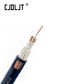
Shielding Mechanism (Letters P / P2): * Shielding layers mitigate electromagnetic interference (EMI) to ensure signal integrity. In power cabling, “P” designates a braided shield, whereas “P2” specifies a copper tape shield, which is the industry standard for industrial power transmission. IEC standards categorize these functional layers into conductor screening, insulation screening, and metallic screens.
Insulation and Sheathing Materials
The selection of insulation and outer sheathing dictates the cable’s environmental resistance and thermal limits:
- YJ (Cross-linked Polyethylene / XLPE): This insulation material provides superior thermal ratings and dielectric strength compared to standard PVC, making it the industry standard for robust commercial and industrial distribution.
- V (Polyvinyl Chloride / PVC): A highly versatile, cost-efficient compounding material used for standard indoor and outdoor protective sheathing.
- Y (Polyethylene / PE): Offers excellent moisture resistance and chemical stability, making it ideal for direct burial, outdoor, or hydro-exposed environments.
- ZR (Flame Retardant): Classified into performance tiers (ZR-A, B, C, D). Class A represents the highest flame-retardant efficacy, mandatory for high-risk, volatile environments.
Mechanical Armoring: The Double-Number Suffix System
The twin numerical suffix at the end of a cable designation denotes the mechanical armoring type (first digit) and the outer jacket material (second digit) in compliance with GB/T 12706 and IEC 60502.
- 22 (Steel Tape Armor + PVC Outer Sheath): Engineered to withstand high radial compressive forces but cannot tolerate longitudinal tensile stress. Recommended for standard underground trench installations.
- 32 (Fine Round Steel Wire Armor + PVC Outer Sheath): Designed to bear significant longitudinal tensile loads. Suitable for vertical shafts, high-drop runs, or marine applications.
- 42 (Thick Round Steel Wire Armor + PVC Outer Sheath): Represents the highest tier of mechanical impact protection and tensile strength, specified for extreme outdoor and high-stress environments.
- 23 / 33 (Steel Tape/Wire Armor + PE Outer Sheath): The inclusion of a PE outer jacket provides superior waterproofing and corrosion resistance, optimizing the armored cable for highly corrosive underground or underwater installations.
- Unnumbered Suffix: Indicates an unarmored configuration (e.g., standard YJV), restricted to indoor tray or conduit installations where mechanical risks are absent.
Specialized Safety Performance Classifications
For high-density, critical infrastructure, specific safety prefixes indicate enhanced compound engineering:
- ZR / FR (Flame Retardant): ZR is standard in GB nomenclature, while FR is utilized in IEC documentation. These compounds prevent flame propagation but may emit halogenated, toxic gases during combustion.
- NH / FE (Fire Resistant): These cables incorporate an internal mica tape barrier. They are certified to maintain circuit integrity for 90 to 120 minutes during active fire conditions (per IEC 60331), securing emergency power for life-safety systems.
- WDZA / WDZB / WDZC (Low Smoke Zero Halogen / LSZH): The modern specification standard for public infrastructure. They emit minimal smoke and zero acid gases during combustion, preventing toxic inhalation in confined areas like subways, hospitals, and high-rise structures. In international procurement, this classification is universally designated as LSZH.