


Understanding the Dielectric Constant of a Cable
The dielectric constant (εᵣ), also known as relative permittivity, is a dimensionless ratio that measures an insulation material’s ability to store electrical energy in an electrostatic field compared to a vacuum. In cable engineering, it is a foundational parameter governed by standards like IEC 60250.
The dielectric constant directly dictates a cable’s capacitance, charging current, and signal propagation speed. For power cables, a lower dielectric constant is preferred to minimize capacitive power losses and leakage currents. For coaxial and data cables, it determines the characteristic impedance (Z₀) and transmission attenuation.
Technical Parameter Matrix: Insulation Material Characteristics
Different insulation compounds exhibit varying dielectric constants, which directly influences their suitability for specific voltage ratings and high-frequency applications at the standard reference frequency of 50 Hz / 60 Hz or high frequencies.
| Insulation Material | Typical Dielectric Constant (εr at 20°C) | Dielectric Dissipation Factor (tanδ) | Max Continuous Operating Temp | Primary Application Scenarios |
| Foamed Polyethylene (Cellular PE) | 1.5 – 1.8 | <0.0002 | 80°C | High-frequency coaxial & data cables (Low attenuation) |
| Solid Polyethylene (PE) | 2.3 | < 0.0003 | 70°C | Telecommunication & radio-frequency (RF) lines |
| Cross-linked Polyethylene (XLPE) | 2.3 – 2.5 | < 0.0005 | 90°C | Medium to Extra-High Voltage (MV/HV/EHV) power cables |
| Polyvinyl Chloride (PVC) | 4.0 – 8.0 | 0.0100 – 0.1000 | 70°C / 90°C | Low Voltage (LV) power, control, and domestic wiring |
| Ethylene Propylene Rubber (EPR) | 2.8 – 3.5 | < 0.0050 | 90°C | Flexible trailing cables, marine, and mining applications |
The Engineering Impacts of εᵣ on Cable Performance
1. Cable Capacitance and Charging Current
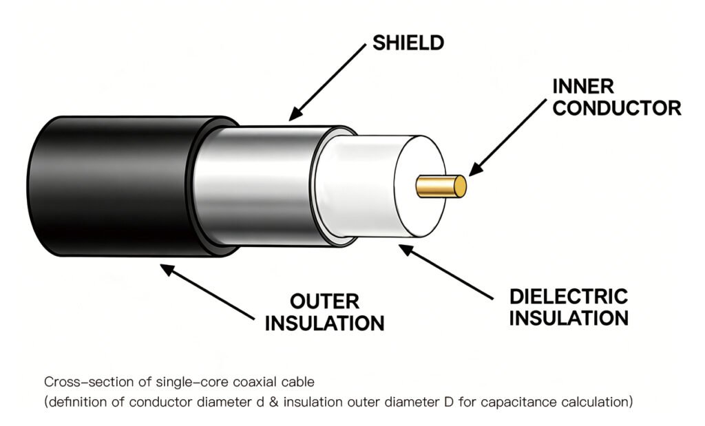
In AC power distribution, a cable acts as a continuous coaxial capacitor. The capacitance (C) of a single-core shielded cable is calculated using the formula:
Where ε₀ is the permittivity of free space, D is the diameter over the insulation, and d is the conductor diameter. A higher dielectric constant (εᵣ) exponentially increases cable capacitance. In Medium and High Voltage systems, this results in a high capacitive charging current (), which causes systemic power losses and reduces the effective ampacity of the cable network even under no-load conditions.
2. Dielectric Power Loss
In high-voltage circuits, insulation experiences continuous molecular polarization flipping at the grid frequency. The power lost per meter as heat inside the dielectric matrix is expressed as:
Because capacitance (C) depends directly on εᵣ, using a high-dielectric material like PVC for high-voltage transmission would cause excessive thermal buildup (), resulting in rapid thermal runaway. This is why XLPE (low ) is globally mandated for MV/HV networks.
3. Velocity of Propagation (Data & RF Cables)
For signal transmission and Ethernet cables, the speed at which an electromagnetic wave travels down the wire depends inversely on the square root of the dielectric constant:
Where c is the speed of light. To achieve fast data transfer rates, minimize signal distortion, and prevent phase shifts, communication cables utilize Foamed PE, injecting microscopic air pockets ( for air) into the polymer matrix to lower the overall effective dielectric constant toward 1.5.