

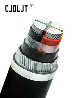
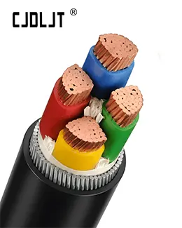
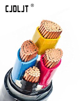
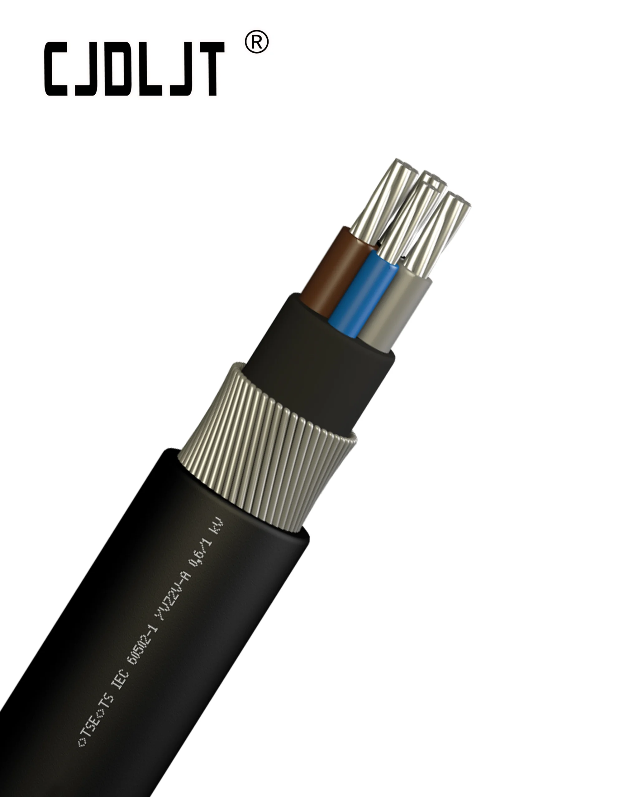

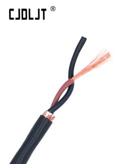

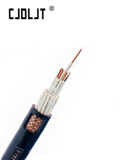
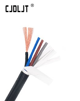
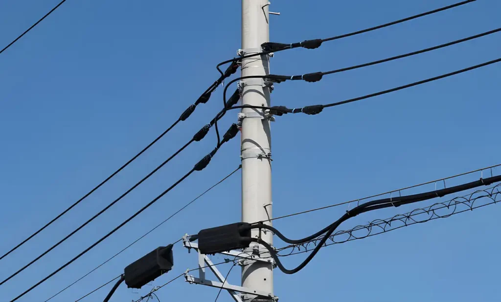
When procuring 1kV Low Voltage Aerial Bundled Cable (ABC), technical parameters dictate operational reliability, system safety, and lifecycle cost efficiency. ABC systems replace bare overhead conductors with insulated aluminum cores wrapped around a neutral messenger. Selecting the correct specification requires evaluating physical layout, electrical loads, mechanical tension, ambient exposure, and regulatory standards to prevent premature insulation degradation, excess voltage drop, or mechanical failure.
Technical Parameter Comparison Matrix
| Technical Parameter | Standard Option / Type A | High-Performance Option / Type B | Impact on Selection & Application |
| Conductor Material | EC-Grade Aluminum (AAC) | Hard-Drawn Aluminum / AAAC Alloy | Determines current carrying capacity, weight, and mechanical tensile strength. |
| Neutral Messenger Type | Bare AAAC / ACSR Messenger | Insulated AAAC / Steel Reinforced | Dictates total bundle breaking strength, corrosion resistance, and earthing profile. |
| Insulation Polymer | High-Density Polyethylene (HDPE) | Cross-Linked Polyethylene (XLPE) | Sets continuous operating temp limit (75°C for HDPE vs 90°C for XLPE). |
| UV & Weather Resistance | Carbon Black Content | Carbon Black Content with Anti-Tracking | Prevents premature polymer degradation and micro-cracking from solar radiation. |
| System Configuration | Self-Supporting (Equal Cores) | Neutral-Messenger Supported | Controls clamp selection, dead-end hardware style, and maximum span length. |
| Applicable Standards | IEC 60502-1 / NFC 33-209 | BS 7870-5 / VDE 0276-626 | Establishes testing limits, core identification (ribbed/printed), and manufacturing tolerances. |
5 Key Factors To Consider Before Ordering
1. System Structural Design & Messenger Type
Specify whether the installation requires a Neutral-Messenger Supported System or a Self-Supporting System. In neutral-messenger configurations, the entire tensile load is carried by a dedicated high-strength Aluminum Alloy Conductor (AAAC) or ACSR core. In self-supporting configurations, mechanical strain is distributed evenly across all insulated phase conductors.
2. Conductor Cross-Sectional Area & Voltage Drop
Calculate phase conductor cross-sections (typically 16 mm² to 150 mm²) based on maximum continuous load current, ambient temperature derating, and permissible voltage drop limits (usually ). Ensure the Neutral Conductor cross-section meets system unbalance and fault current requirements.
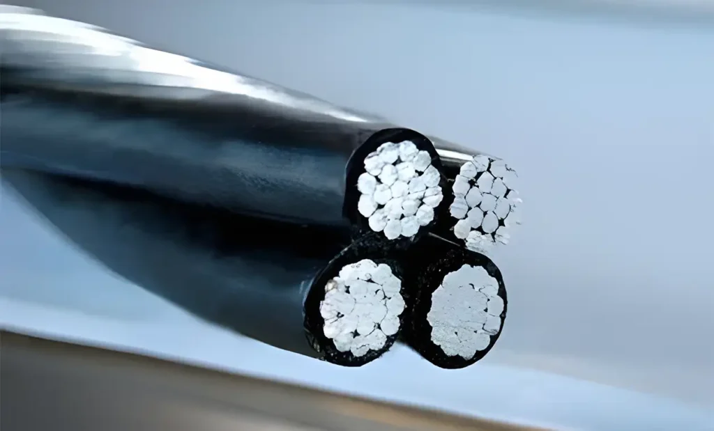
3. Insulation Material & Environmental Endurance
Select Cross-Linked Polyethylene (XLPE) over standard PVC or PE for higher thermal stability, offering a 90°C continuous operating threshold and 250°C short-circuit limit. Verify that insulation compounds contain a minimum of 2.0% to 2.5% carbon black content for severe UV radiation and outdoor atmospheric exposure.
4. Span Length, Wind Loading & Mechanical Tension
Evaluate site-specific mechanical forces including maximum pole span lengths, ruling span distances, and local wind or ice loading profiles. Match the minimum breaking load (MBL) of the messenger core to the maximum calculated installation sag tension to eliminate conductor fatigue.
5. Accessory Compatibility & Core Identification Method
Ensure the phase identification method matches utility standards—typically longitudinal surface ribs (1, 2, or 3 ribs) or clear color/numerical printing. Verify full mechanical and electrical compatibility with Insulation Piercing Connectors (IPCs), anchor dead-end clamps, and pre-insulated suspension assemblies to prevent sheath damage or contact resistance heating.