



High-Voltage Cable Impulse Withstand Voltage Test Specifications
According to international standards IEC 60840 (for cables rated up to 150 kV and IEC 62067 (for cables rated above 150 kV up to 500 kV, the lightning impulse withstand voltage test must be conducted at a controlled elevated temperature—specifically with the cable conductor maintained between 90°C and 95°C (or the maximum rated operating temperature of the XLPE insulation).
The standard mandates that the test sequence must consist of 10 consecutive positive polarity impulses followed immediately by 10 consecutive negative polarity impulses at the full specified test voltage (Up). The wave shape must conform to a standard lightning impulse with a front time (T1) of 1.2 μs±30% and a time-to-half value (T2) of (T1) of 1.2 μs±30% (commonly designated as a 1.2/50 μs wave). No dielectric breakdown or flashover may occur during any of the 20 applied impulses for the cable system to pass.
Technical Parameter Matrix: Impulse Waveform & Sequencing
The structural boundaries for executing impulse verification tests on high-voltage system typologies are outlined below:
| Voltage Class (Um) | Standard Reference | Required Peak Voltage (Up) Examples | Required Impulses (Positive) | Required Impulses (Negative) | Permissible Wavefront / Tail Tolerances |
| 110 kV to 132 kV | IEC 60840 | 550 kV / 650 kV | 10 | 10 | T1: ±30%, T2: ±20% |
| 220 kV to 230 kV | IEC 60840 | 1050 kV | 10 | 10 | T1: ±30%, T2: ±20% |
| 380 kV to 500 kV | IEC 62067 | 1425 kV / 1550 kV | 10 | 10 | T1: ±30%, T2: ±20% |
Root Cause Analysis of Impulse Breakdown Failures
Space Charge Accumulation Effects
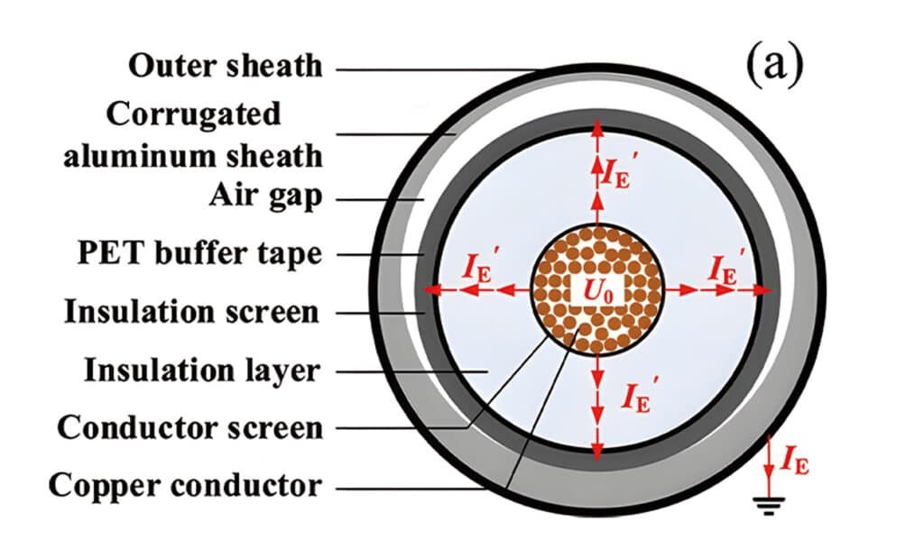
The requirement to apply 10 positive impulses followed by 10 negative impulses is designed to stress the insulation system during the polarity transition. Under high-voltage DC or unipolar impulse stress, homocharges (space charges with the same polarity as the electrode) inject into the XLPE bulk near the Conductor Screen or insulation screen.
When the generator abruptly switches to negative polarity, the trapped positive space charge field aligns with the new external negative field. This superposition drastically amplifies the localized electric field gradient (Emax), easily triggering electrical tree initiation if there are structural flaws in the polymer.
Common Breakdown Morphologies and Manufacturing Flaws
- Electrical Treeing from Contaminants: If microscopic metal fragments (e.g., copper or iron dust from drawing dies) cross into the XLPE matrix during three-layer co-extrusion, they act as infinite field enhancers. The resulting breakdown track features a dense, bush-like tree structure radiating outward from the particle.
- Micro-Void Discharge Paths: Insufficient curing pressure or moisture entry during a wet vulcanization process leaves microscopic gas-filled voids within the insulation. Under the steep wavefront of a lightning impulse (1.2 μs), the air inside these voids ionizes instantly. This produces localized partial discharge tracks that quickly pierce the remaining insulation wall, leaving a clean, straight carbonized borehole.