


A neutral conductor in Aerial Bundled Conductor (ABC) overhead lines is the dedicated auxiliary core in four-core ABC cable assemblies.
It safely carries unbalanced load return current and stabilises phase-to-neutral operating voltage across the low-voltage distribution network.
It serves as a reliable common return path for all single-phase branch circuits and provides a clear, low-resistance route for accidental fault current.
This steady reference potential effectively improves overall on-site power quality and strengthens operational safety for line crews and connected assets.
The neutral conductor is always sized to withstand the maximum continuous unbalanced current and short-term fault current expected on the feeder.
It is permanently bonded to the earth electrode at the distribution transformer or upstream substation, establishing a stable zero-voltage reference point for the entire overhead system.
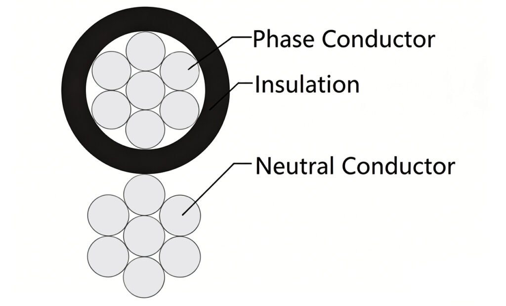
Depending on the line design, the neutral core can be fully insulated or bare within the bundle to control corona discharge, maintain uniform inter-core spacing, and optimise electromagnetic field distribution along the route.
Definition, role, and terminology
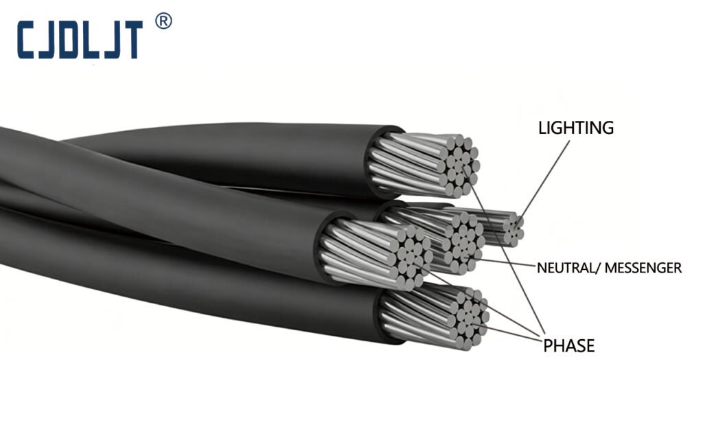
Neutral conductor: A dedicated fourth core integrated into four-core ABC cables, designed to carry return current and provide a stable voltage reference for all phase conductors.
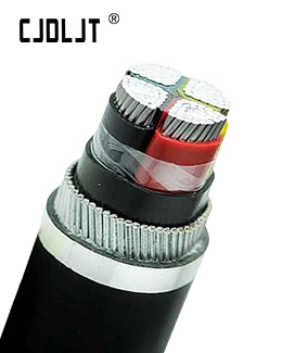
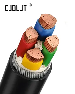
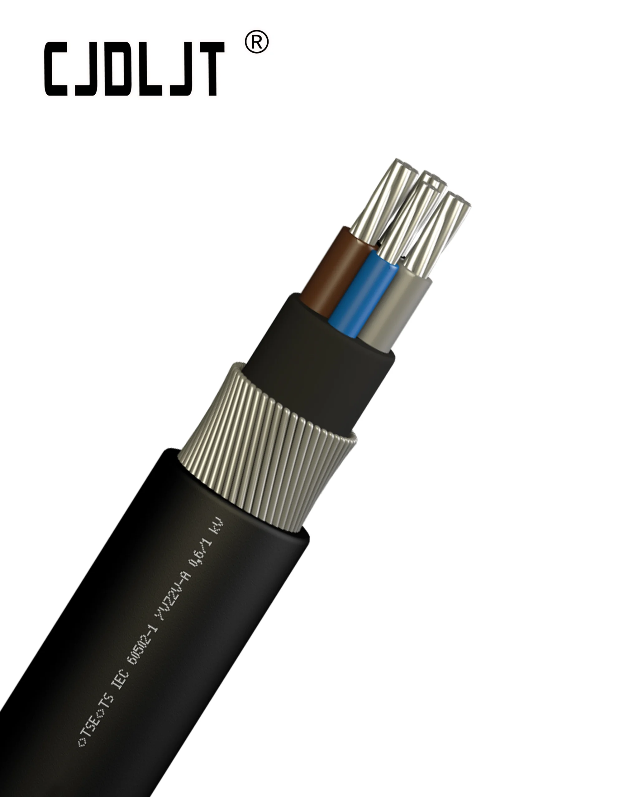
Four-core ABC configuration: Standard assembly consisting of three fully insulated phase conductors (A, B, C) plus one matched neutral conductor. The neutral can be centrally positioned or arranged according to manufacturer-specific bundled mechanical designs.
System grounding: The neutral core is solidly bonded to the local earth grid at transformers or substations. This fixed zero potential reference ensures fast, reliable fault tripping and protects overhead equipment from abnormal voltage drift.
Electrical behavior and safety implications
Neutral current characteristics: Neutral current equals the vector sum of all three phase currents under unbalanced loading conditions. When three-phase loads are evenly balanced, residual neutral current drops to nearly zero.
Controlled fault return path: The neutral conductor creates a predictable, low-impedance path for earth fault current. This allows protective relays to detect abnormal conditions instantly and isolate faulty sections quickly.
Corona and noise control: Using an insulated neutral core together with optimised inter-conductor spacing minimises electric field concentration. This reduces corona discharge, audible operational noise, and unnecessary power losses along overhead routes.
Design and installation considerations
Conductor cross-section sizing: The neutral wire cross-sectional area must be fully rated to sustain continuous unbalanced load current and withstand short-duration fault surges without thermal overheating or mechanical degradation.
Insulation material selection: Insulated neutral designs are preferred to suppress corona activity and reduce ambient noise. The insulation voltage rating must strictly match the nominal operating voltage of the full ABC overhead system.
Precision bundling geometry: Controlled core spacing and symmetrical conductor layout directly improve electromagnetic field uniformity. This simple measure further lowers corona risk and strengthens long-term mechanical stability.
Compatible termination hardware: All cable lugs, connectors and jointing accessories must be mechanically and electrically compatible with the neutral conductor type, whether insulated or bare, and matched to its exact cross-section.
Routine on-site inspection: Regular maintenance checks must cover insulation surface integrity, shielding continuity, bundled spacing consistency, and permanent grounding connection health to avoid hidden operational risks.
SOP / Checklist (Neutral conductor in ABC design and installation)
- Confirm the full overhead system layout and verify the adoption of standard four-core ABC layout (A, B, C plus dedicated neutral) or approved alternative neutral integration structure.
- Accurately calculate the maximum continuous unbalanced phase current and prospective short-circuit fault current to determine the minimum required neutral conductor cross-section.
- Finalise the neutral insulation scheme; select fully insulated neutral for enhanced corona suppression and stable spacing, and double-check compliance with the system voltage class rating.
- Select neutral conductor raw material — aluminium alloy or copper — based on overall line mechanical load limits, total project cost, and long-term corrosion resistance requirements.
- Design and confirm precise bundling geometry, arranging the neutral position inside the cable bundle to optimise electromagnetic field distribution and minimise corona generation.
- Verify the complete neutral earthing arrangement; ensure solid neutral-to-earth bonding at transformers or substations with full compliance to safety clearance and earthing resistance standards.
- Specify fully rated termination accessories, including compression lugs, joint sleeves and clamps, matching the neutral conductor’s material type and approved cross-section size.
- Carry out mandatory on-site quality acceptance tests: insulation resistance integrity testing, full neutral conductor continuity verification, and reliable earth-bond connection confirmation.
- Complete formal commissioning and archive all technical records, including conductor cross-section data, insulation type, exact grounding point locations, and full test reports for future maintenance and relay parameter reference.