

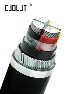
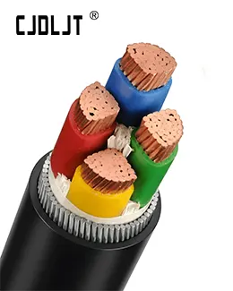
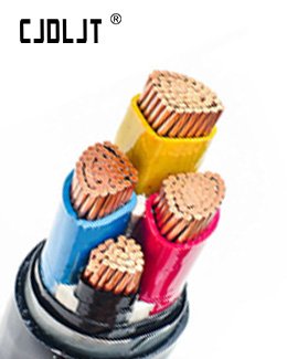
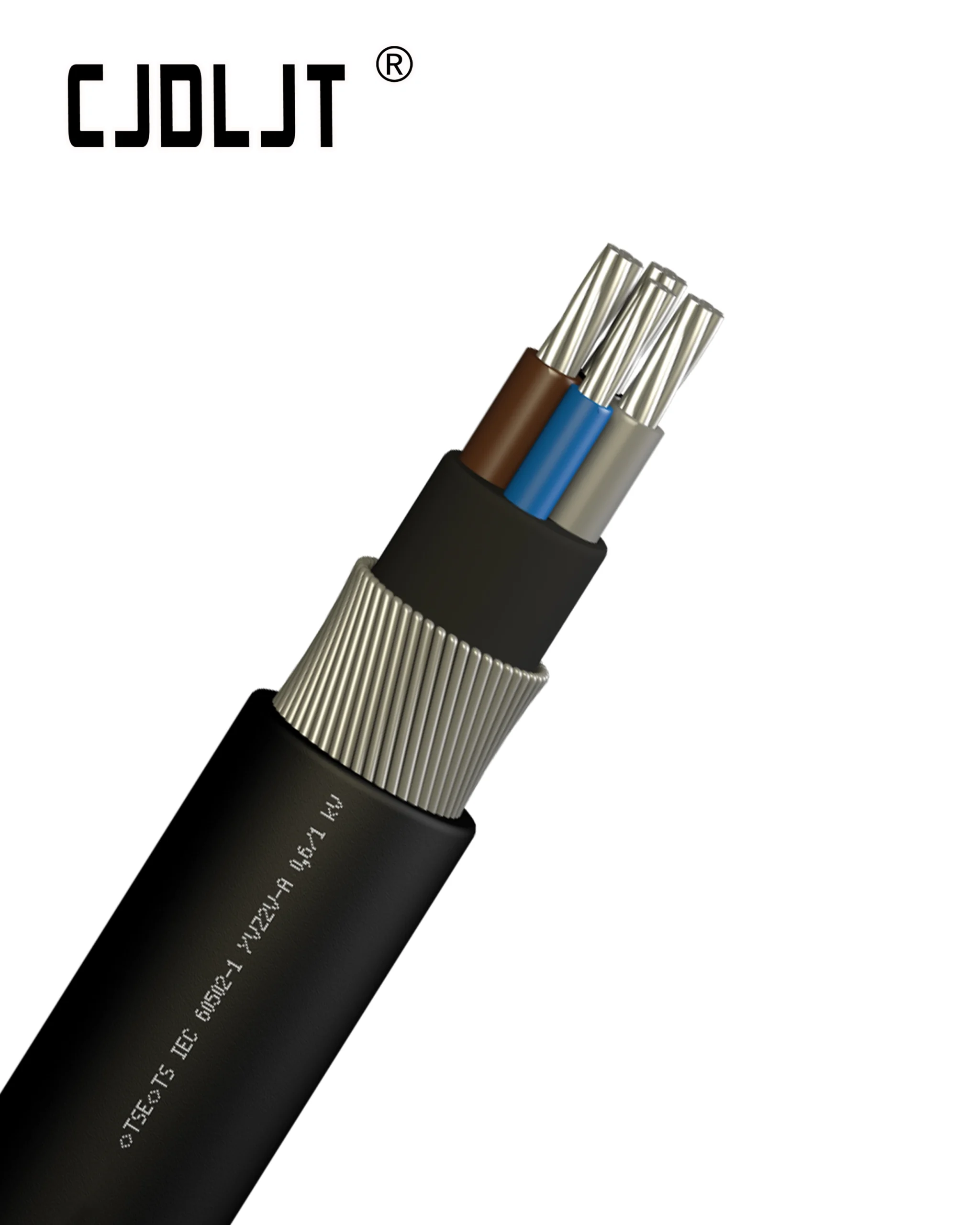

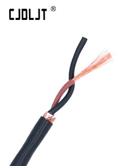

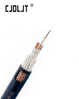
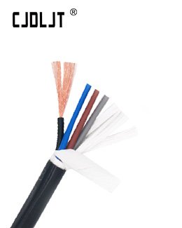
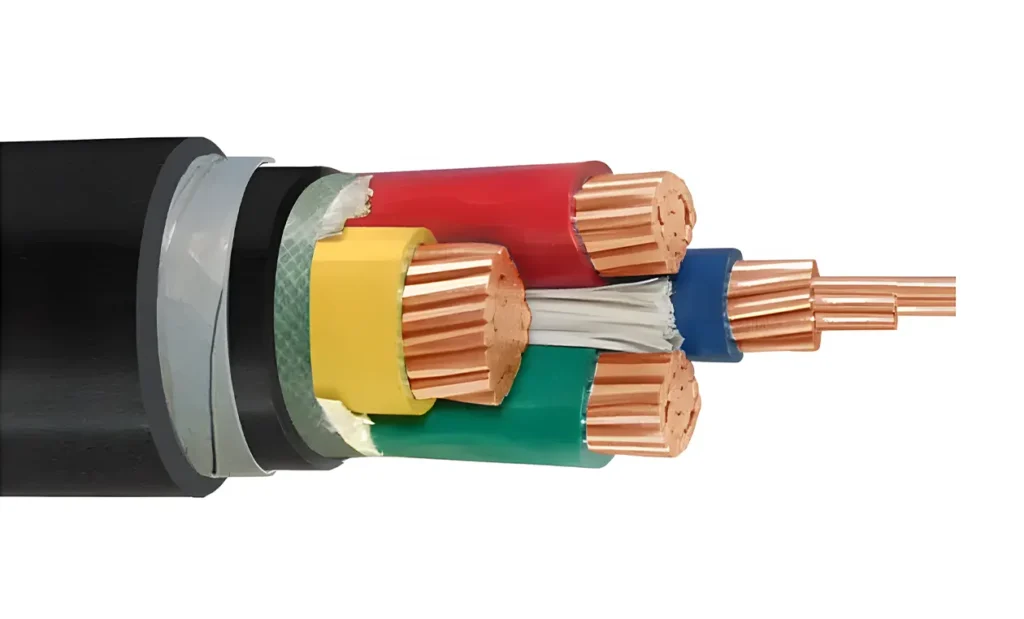
When directly burying N2XBY DSTA (Double Steel Tape Armour) cable, precautions must focus on protecting the outer PVC sheath and maintaining mechanical cable geometry under soil compaction. N2XBY is an [1]compliant 0.6/1 kV underground power cable featuring plain annealed copper conductors, XLPE insulation (90°C rating), PVC inner bedding, double galvanized steel tape armour, and a PVC outer sheath. Direct burial requires a minimum trench depth of 0.7–1.0 meters, a 100 mm stone-free sand bedding layer, mechanical protective cable cover tiles, and compliance with the minimum bending radius of to prevent armour buckling, moisture ingress, and thermal hotspot formation.
Direct Burial Technical Specification Matrix
| Parameter / Operational Specification | Direct Burial Requirement / Standard | IEC / Industry Standard Reference |
| Minimum Trench Depth (Low Voltage) | 0.7 m (Footpaths/Gardens) / 1.0 m (Road Crossings) | [2] / Local Utility Codes |
| Trench Bedding Sand Layer | 100 mm stone-free washed sand above & below cable | National Electrical Installation Codes |
| Minimum Bending Radius | (During Laying) / (Fixed Position) | IEC 60502-1 / VDE 0276-603 |
| Max. Continuous Operating Temp. | 90°C (Conductor continuous XLPE rating) | IEC 60502-1 |
| Max. Short-Circuit Temperature | 250°C () | IEC 60502-1 Thermal Limits |
| Armour Grounding Requirement | Both ends bonded to protective earth (PE) | IEC 60364-4-41 / [3] |
| Mechanical Hazard Marker | Warning tape placed 250–300 mm above protective tiles | EN 12613 / Utility Underground Standards |
| Soil Thermal Resistivity Base | Standard design rating at | IEC 60287 Cable Ampacity Sizing |
Trench Preparation and Sand Bedding Integrity
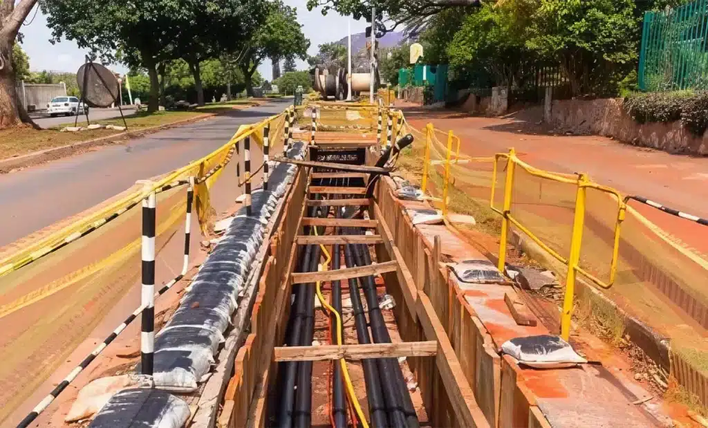
Direct burial exposes the PVC outer sheath (Y) to sharp aggregates, soil shifting, and static ground compression.
- Bottom Trench Prep: The trench base must be backfilled with a 100 mm layer of well-compacted, stone-free sand or fine screened earth prior to cable laying.
- Backfill Envelope: Once the N2XBY cable is pulled, a second 100 mm sand layer must cover the top of the cable before surrounding native backfill is added. This sand cushion prevents sharp rocks from pressing through the outer jacket under soil settlement loads.
- Prohibited Sharp Point-Loads: Direct contact with crushed concrete, gravel, or shale forces local pressure points through the outer PVC jacket, exposing the galvanized steel tape to moisture oxidation and localized ground-fault leakage.
Mechanical Bending and Pulling Tension Limits
Although the Double Steel Tape Armour (DSTA) provides superior 100% continuous coverage against surface crushing and rodent penetration, steel tape armour offers low tensile force resistance and poor torsional tolerance compared to Steel Wire Armour (SWA).
- Minimum Bending Radius: Maintain a strict minimum bending radius of during trench pulling. Violating this limit causes the overlapping steel tapes to ride over one another, resulting in armour tape buckling, tears in the PVC inner bedding, and dielectric stress on the internal XLPE insulation cores.
- Pulling Eyebolt Attachment: Pulling tension must be applied directly to the annealed copper conductors using a pulling eye, rather than pulling from the outer sheath or armour layer. Maximum pulling tension should not exceed of total conductor cross-sectional area.
Mechanical Protection Tiles and Hazard Warning Systems
Because N2XBY uses steel tape armour rather than structural wire armour, it cannot withstand direct impact from heavy excavation machinery (such as backhoes or trench diggers).
- Protective Cover Tiles: Place high-impact concrete cable cover tiles or heavy-duty polyethylene (HDPE) protection plates 100 mm above the sand cushion layer.
- Underground Warning Tape: Install a brightly colored, marker-imprinted warning tape (e.g., “CAUTION: ELECTRIC CABLE BURIED BELOW”) 250 mm to 300 mm above the protective tiles to serve as an early-detection visual barrier during future site excavation.
Armour Equipotential Bonding and Sheath Integrity Testing
- Equipotential Earthing: Both ends of the double steel tape armour layer must be securely bonded to the station or distribution system’s protective earth (PE) busbar using purpose-built armour grounding clamps or brass cable glands. This provides an effective low-impedance path to trip protective devices during high-voltage earth-fault events.
- Post-Laying Oversheath DC Test: Before backfilling the upper trench, perform a 4 kV DC voltage test for 1 minute between the steel tape armour and the surrounding earth/ground pursuant to IEC 60502-1. A successful test confirms that pulling operations caused zero tears or micro-punctures in the PVC outer sheath.
CJDL CABLE Engineering Insight
For direct-burial N2XBY DSTA cable installations, adhering to the laying bending radius and applying a 100 mm stone-free sand envelope above and below the cable are essential to prevent armour buckling and oversheath damage under compaction. Grounding both ends of the DSTA layer to PE and validating the sheath with a 4 kV DC test prior to final backfill ensures long-term operational reliability. CJDL CABLE manufactures and routinely tests all N2XBY DSTA cables to IEC 60502-1 standards for heavy-duty underground distribution.
References
[1] Wikipedia. IEC 60502[EB/OL]. 2026-09-29.
[2] Wikipedia. IEC 60364[EB/OL]. 2026-09-29.
[3] Wikipedia. BS 7671[EB/OL]. 2026-09-29.