
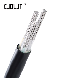

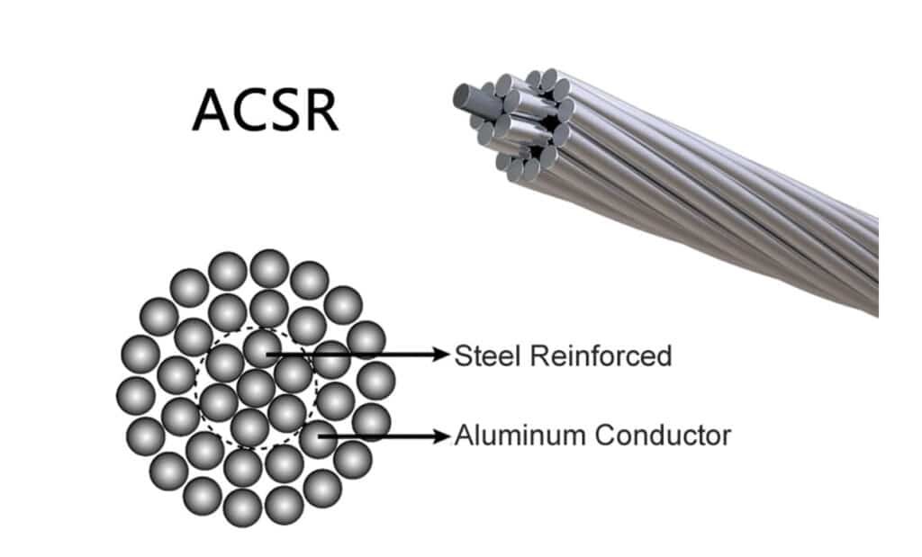
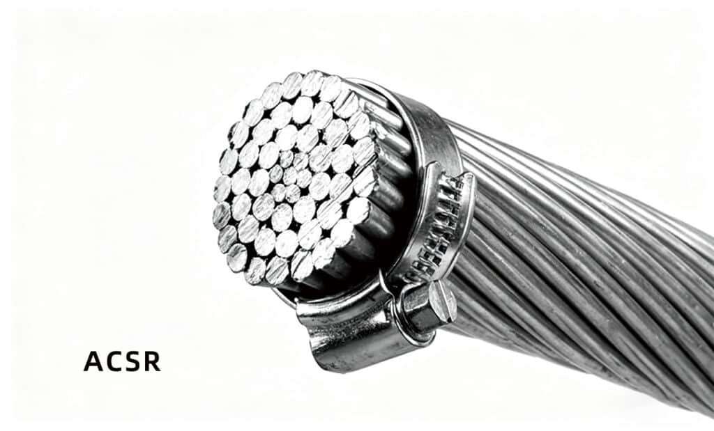
ACSR stands for Aluminum Conductor Steel Reinforced — the most widely used bare overhead power line conductor. It has a simple but effective structure: Aluminum outer strands carry electric current. A galvanized steel core provides strong tensile strength. This combination allows long‑distance power lines to withstand wind, ice, and sag without insulation. Versions with high‑strength alloys further improve its strength‑to‑weight ratio. ACSR is commonly used for MV and HV transmission from 6 kV up to 230 kV, complying with international standards such as IEC 61089.
Construction and Materials
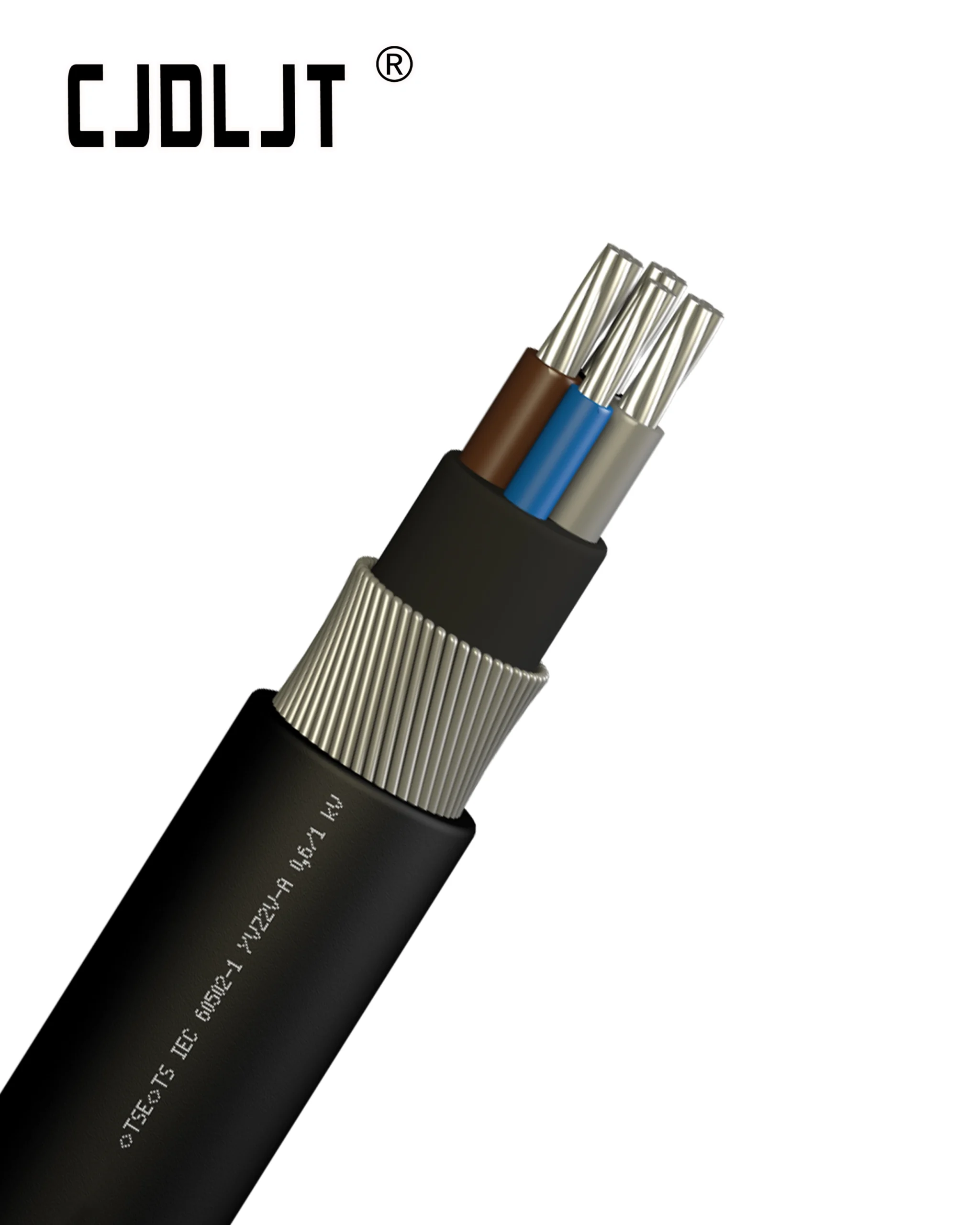
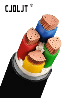
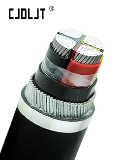
Conductor structure: Aluminum strands around a central galvanized steel core.
Core material: Galvanized high-tensile steel.
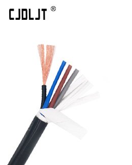
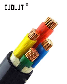
Insulation/Jacket: None (bare conductor).
Stranding: Multi-strand aluminum around the steel core; hexagonal or round configurations are common.
Corrosion protection: Steel core galvanization; aluminum strands are corrosion-resistant alloy.
Typical uses: Long-span MV/HV overhead transmission and distribution lines.
Applications, Standards, and Performance
Applications: Long-span overhead lines where sag control and mechanical strength are critical.
Standards (global/region): IEC 61089; NESC (US); regional equivalents; cross-reference with IEC 60502 family for LV derivatives when applicable.
Performance characteristics:
High tensile strength enables long spans and heavy loading.
Ampacity per cross-section is influenced by the steel core; typically lower per cross-section than all-aluminum equivalents of the same diameter.
Suitable for environments with significant wind, ice, and mechanical loading.
SOP / Checklist (Selection, Installation, Testing)
- Define voltage & span requirements
Confirm medium/high voltage class, target span length; assess terrain, wind/ice loads and support structures. - Select conductor & cross-section
Choose suitable ACSR (aluminum & steel core) to meet tensile and current capacity; compare with AAC/AAAC for mechanical and ampacity trade-offs. - Determine mechanical parameters
Set Minimum Breaking Load (MBL) and allowable tension; define core diameter and aluminum strands to satisfy sag and wind requirements. - Plan routing & supports
Check pole/tower height, guying, anchors, spacers and messenger needs; ensure installation and maintenance accessibility. - Inspection & testing
Visually check strand damage, core corrosion and coating wear; post-installation electrical tests (continuity, resistance) as required. - Terminations & splices
Select ACSR-compatible termination kits and hardware; use mechanical splices that maintain sag and conductor integrity. - Installation guidelines
Use proper pulling methods, avoid sharp bends, follow sag‑to‑span ratios; maintain minimum bend radius (typically 12× conductor diameter for ACSR). - Commissioning & documentation
Verify sag, tension, clearance and phase identification post-installation; record route, specs, MBL and maintenance schedule for asset management.