
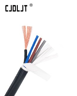
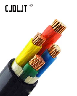
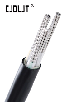

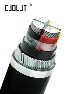
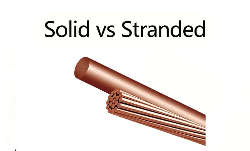
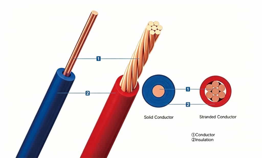
Stranded conductors are composed of many fine wires twisted together to form a single conductor, while solid conductors are a single, solid wire of equivalent cross-sectional area.
Stranded conductors offer superior flexibility, fatigue resistance, and vibration tolerance, making them ideal for dynamic routing or portable/applied-flex applications.
Solid conductors provide stiffness and ease of termination in fixed installations.
Electrically, DC resistance per cross-section is essentially the same; at 50/60 Hz, AC resistance differences are typically small and size-dependent.
The choice depends on installation environment, termination method, and mechanical demands rather than a large difference in conductivity.
Definition, construction, and terminology
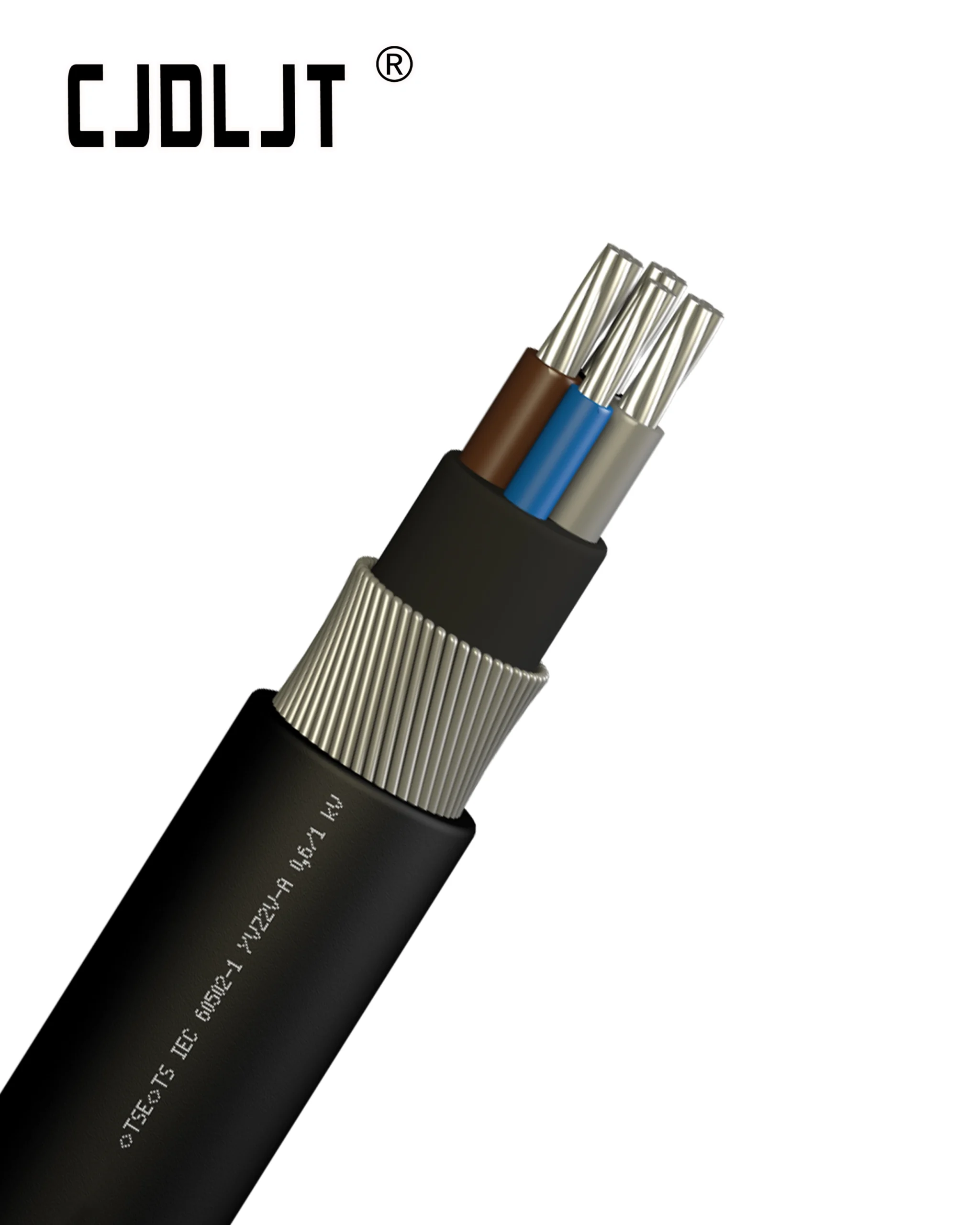
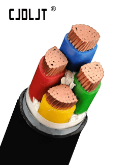
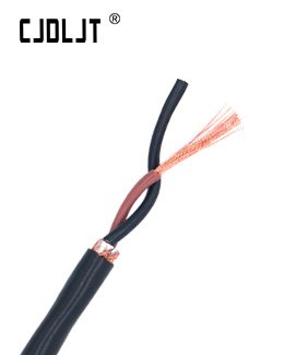
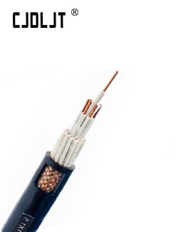
Stranded conductor: multiple fine wires (e.g., 7×7, 19×7) twisted to form the conductor; can be tinned for corrosion resistance.
Solid conductor: a single prism of copper or aluminum; used where minimal flexing is anticipated.
Common standards reference: IEC 60228 classifies conductors as solid (Class 1) or stranded (Class 2) for insulated conductors.
Electrical and mechanical performance implications
Resistance: For a given cross-sectional area, DC resistance is essentially the same between stranded and solid. AC resistance can differ slightly due to skin and proximity effects, but this is typically negligible for LV power cables.
Flexibility and fatigue: Stranded is preferred where repeated bending, vibration, or complex routing occur; solid is prone to work-hardening and cracking under frequent flexing.
Termination: Stranded conductors require ferrules or appropriate crimp/lug designs to ensure reliable contact; solid conductors align well with screw terminals and some fixed lugs.
Applications and installation considerations
Use stranded when the cable must bend, move, or be routed through flexible conduits, equipment in motion, or panel interconnects.
Use solid for clean, fixed runs in walls, conduits, trays, or other installations with little to no movement.
Consider environmental factors (vibration, temperature cycling, moisture) and termination hardware compatibility when selecting.
SOP / Checklist (Conductor Selection & Installation)
1.Define installation dynamics
Is the cable fixed, or will it flex/bend frequently? Note expected bend radii.
2.Select conductor type based on movement
Stranded for flexible, portable, or vibration-prone routes; solid for fixed/wall installations.
3.Verify termination method compatibility
Confirm lugs, ferrules, or screw terminals are rated for the chosen conductor type (multi-strand vs solid).
4.Check bend radius requirements
For stranded: minimum bend radius often 6–8× cable diameter; for solid: 8–12× diameter (consult manufacturer).
5.Assess corrosion/oxidation considerations
Stranded conductors in harsh environments may benefit from tinning; select appropriate insulation and jacket materials.
6.Confirm gauge and insulation consistency
Ensure insulation thickness and jacket ratings match service temperature and voltage requirements.
7.Perform pre-installation inspections
Inspect cut ends, strand integrity, and termination readiness; document any damaged conductors.
8.Conduct electrical tests post-termination
Continuity, insulation resistance, and, where applicable, contact resistance at terminals.
9.Document installation traceability
Record conductor type, cross-section, termination method, and test results for warranty/audit purposes.