


Why DC Resistance is the Ultimate Metric for Cable Quality
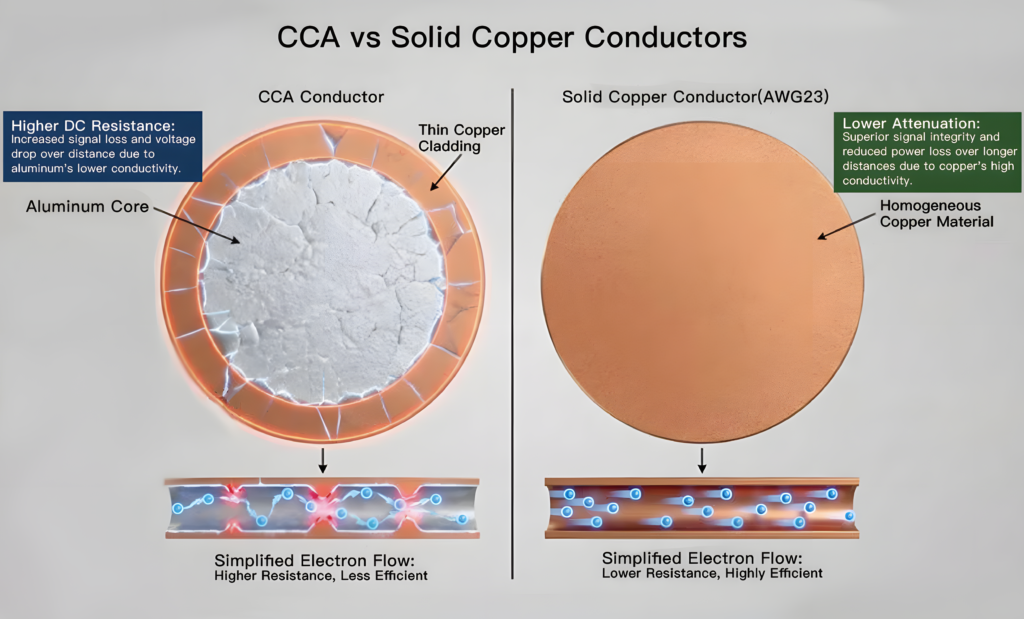
Conductor DC resistance (R_DC) is the single most critical indicator of cable quality because it directly measures material purity, manufacturing precision, and operational safety. It cannot be faked or compensated for by heavy insulation or branding. If a cable fails its DC resistance verification according to IEC 60228, it means the manufacturer either compromised on the copper/aluminum quality or skimped on the actual cross-sectional area of the conductor.
Low DC resistance guarantees that a cable will operate efficiently within its thermal limits. High DC resistance introduces excessive energy loss, accelerated thermal degradation, and a heightened risk of catastrophic electrical fires.
Technical Parameter Matrix: The Cost of Substandard DC Resistance
When a cable has elevated DC resistance due to poor quality control, it directly compromises the electrical and physical integrity of the entire installation.
| Cable Attribute | Compliant Low-Resistance Cable | Substandard High-Resistance Cable | Operational Impact |
| Material Quality | 99.9% Pure Annealed Copper | Impure or scrap copper alloys | Higher baseline resistivity (ρ), causing immediate voltage drops. |
| Cross-Sectional Area | Exact nominal area (e.g., 16 mm²) | “Undersized” conductor core | Increased current density, forcing the cable to run hotter. |
| Power Dissipation ($I^2R$) | Optimized; within thermal design | Excessive; converted to wasted heat | Unnecessary energy costs and reduced system efficiency. |
| Insulation Lifespan | 25+ Years (Operates ≤90°C for XLPE) | Severely Reduced (Thermal degradation) | Premature cracking, embrittlement, and dielectric breakdown. |
| Voltage Drop Verification | Within allowable <=3% or <=5% limits | Excessive voltage drops over long runs | Equipment malfunction, motor stalling, and erratic control signals. |
The Chain Reaction of DC Resistance Failure
1. The Material Deficit (The Root Cause)
Substandard manufacturers often lower production costs by using recycled, unrefined copper containing high levels of oxygen or iron impurities, or by subtly reducing the outer diameter of the strands (“undersizing”). Both tactics cause the actual DC resistance to spike above the legal maximums dictated by standards like BS 5467 or VDE 0295.
2. The Thermal Catalyst (Joule Heating)
According to Joule’s First Law, the thermal energy generated in a conductor is calculated as:
Where P is power loss in watts, I is the operating current, and R is the DC resistance. Because the power loss scales quadratically with current, even a fractional increase in resistance (R) exponentially boosts the heat generated within the core of the cable.
3. Accelerated Thermal Aging
Cables insulated with XLPE (Cross-linked Polyethylene) are engineered to withstand a continuous maximum operating temperature of 90°C. If a high-resistance conductor pushes the internal temperature to 105°C or 110°C, a process of accelerated polymer cross-link degradation begins. The insulation becomes brittle, loses its tensile strength, and eventually cracks under physical or electrical stress.
4. Dielectric Breakdown and Fire Risk
Once the insulation degrades or deforms due to conductor overheating, its dielectric strength collapses. This leads to phase-to-phase or phase-to-earth short circuits. In worst-case scenarios, the sustained thermal energy acts as an ignition source, causing electrical fires—a risk heavily mitigated by utilizing certified Low Smoke Zero Halogen (LSZH) compounds, which still rely entirely on a cool-running, low-resistance core to remain safe.
3-Step Quality Audit for Sourcing Compliant Cables
Procurement and engineering teams should utilize this quick audit checklist to ensure incoming cable shipments meet global quality baselines.
- Mandate Factory Acceptance Test (FAT) Reports: Cross-check the recorded R_20 values on the manufacturer’s test certificates against IEC 60228 Class 2 (for stranded fixed installations) or Class 5 (for flexible applications).
- Conduct Independent Type-Testing: Send a random 5-meter sample from the job site to a third-party laboratory (such as BASEC or UL) to run an independent 4-wire Kelvin bridge resistance test.
- Inspect the Conductor Geometry: Measure individual strand diameters using a calibrated micrometer to ensure the aggregate cross-sectional area matches the stamped cable sheath marking.