

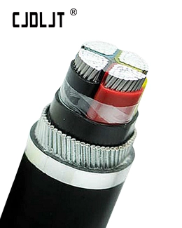
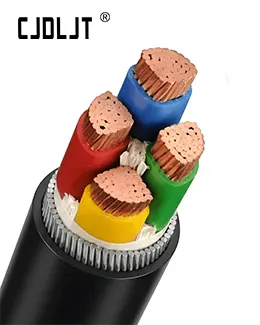
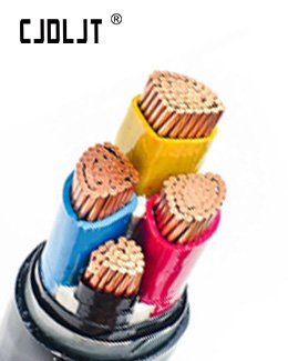
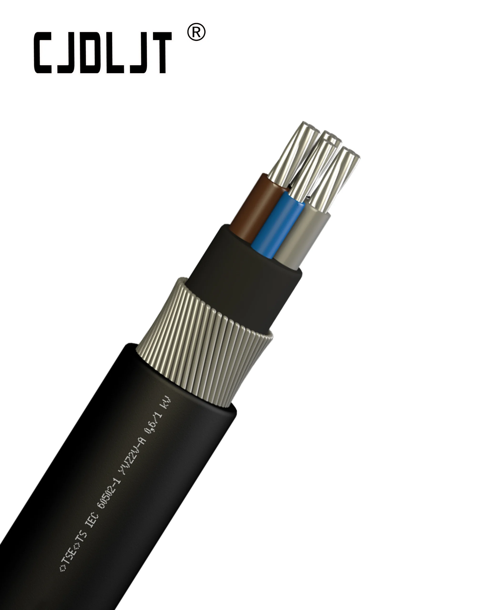


Direct‑buried armoured power cables are widely adopted in industrial parks, urban distribution networks and rural power upgrading projects. Compared with cable‑duct laying, direct‑buried solutions cut engineering costs and shorten construction cycles. However, once buried underground, fault location, excavation and repair become extremely costly and disruptive.
Many engineers mistakenly believe that armouring alone can handle all underground risks. In fact, steel tape or steel‑wire armour only provides mechanical defence; soil corrosion, external excavation damage, water penetration, rodent attack and improper grounding can still trigger premature cable failure. This blog highlights critical protection‑oriented design considerations to extend service life and reduce hidden operational risks for direct‑buried armoured power cables.
1. Rational selection of armour and outer‑sheath structure according to soil environment
“Armoured” is a general concept. Different armour types fit distinct underground geological conditions, and the outer sheath determines anti‑corrosion performance for the metallic armour layer.
- Steel Tape Armour (STA/DSTA): Mainly resists compressive impact forces. Suitable for common soil zones without heavy tensile stress. Not recommended for ground‑subsidence‑prone areas or locations subject to large pulling forces.
- Steel Wire Armour (SWA): Delivers both compression and tensile resistance. Ideal for sites with possible ground displacement, river‑crossing burial and farmland zones. It also offers better defence against rodent and termite gnawing damage.
- Aluminium Wire Armour (AWA): Specially for single‑core AC power cables, to avoid dangerous eddy‑current heating inside magnetic steel armour.
Outer‑sheath material selection:
- Standard PVC outer sheath for neutral‑pH common soil;
- HDPE high‑density polyethylene sheath preferred for corrosive soil, saline‑alkali land or wet ground to prevent galvanic corrosion of steel armour;
- For severely aggressive soil environments, additional anti‑corrosive coating or enhanced sheath thickness shall be specified.
Important note: Armour cannot work without intact outer sheath. If the outer sheath gets damaged during transportation or laying, underground moisture will corrode the armour and gradually destroy internal insulation.
2. Trench design and bedding protection details
Even high‑quality armoured cables can be damaged by point‑loading pressure from sharp stones in backfill soil. Trench design and bedding layer configuration form the primary physical protection barrier.
- Burial depth compliance: In ordinary non‑frozen regions, minimum burial depth should reach 0.7 m measured to cable outer‑sheath surface. For farmland frequently disturbed by farming operations, depth shall increase to at least 1.0 m. In cold frost‑prone zones, cables must sit below the frost line to avoid frost‑heave mechanical stress.
- Trench base treatment: Remove rocks, bricks and hard debris from trench bottom. Lay a 100 mm thick cushion layer of fine sand or soft sifted soil before cable placement. After laying the cable, cover it with another 100 mm fine sand layer to wrap the whole cable circumference. Hard backfill materials must never directly contact the cable outer sheath.
- Mechanical cover protection: Place concrete cable cover slabs or heavy‑duty protective tiles above the sand layer. This blocks pressure from future excavation, construction machinery and surface loads.
- Warning marker installation: Lay bright‑coloured plastic warning tape 300‑400 mm below finished ground level within backfill. The tape alerts future excavation crews of buried cable presence and greatly reduces accidental dig‑through incidents.
3. Protection requirements for special crossing sections
Road crossings, pipeline intersections and building foundation crossings represent high‑risk segments for direct‑buried cables, requiring extra protective design measures:
- When crossing public roads or driveways: Route the armoured cable through rigid protective pipes. The pipe inner diameter should be no less than 1.5 times cable outer diameter. Both pipe ends shall be sealed to stop water, mud and small animals entering the pipe cavity.
- Intersections with heat pipelines: Maintain sufficient safety clearance; avoid parallel laying alongside heating pipes. Where intersection is unavoidable, ensure vertical clearance meets project technical specifications to prevent cable over‑aging caused by heat conduction.
- Keep safe separation distance from building foundations and other underground utilities to avoid external squeezing or chemical contamination.
4. Mechanical protection during cable pulling and laying process
Protection design does not stop at trench drawings; construction‑phase mechanical constraints are equally critical. Improper pulling and bending will cause invisible armour deformation and sheath cracking that only fails years later.
- Strictly follow minimum bending radius limits during laying. Over‑bending causes steel‑tape overlap, armour buckling and hidden micro‑cracks in inner bedding and insulation layers.
- Apply pulling tension on conductor pulling‑eyes rather than pulling force onto outer sheath or armour, to prevent armour‑sheath separation.
- Avoid dragging cables directly over sharp trench edges or rock surfaces. Protect outer sheath from abrasion damage throughout handling.
5. Armour grounding design for safety protection
Armour metal layers must implement correct grounding design, otherwise the mechanical protective layer cannot fulfil its safety‑protection function under fault conditions.
- Multi‑core armoured power cables for direct burial: Metallic armour shall be reliably grounded at both cable ends. When internal insulation breaks down and live conductors touch the armour, the grounded armour guides fault current to earth and triggers over‑current protection devices to cut off power supply quickly, preventing electric‑shock hazards.
- Special reminder for single‑core AC cables: Do not use magnetic steel‑tape or steel‑wire armour, and strictly follow professional specifications for non‑magnetic armour grounding arrangement to avoid continuous circulating current heating on the armour layer.
- Use qualified armour clamping fittings or copper‑braided jumpers for grounding connection points; ensure low‑resistance electrical continuity along the full armour length.
6. Anti‑corrosion, moisture‑proof and pest‑resistant protection design
Many direct‑buried cable failures are not caused by external impact, but by long‑term underground environmental erosion.
- Anti‑corrosion: If local soil shows corrosive properties (acidic, saline‑alkali, industrial polluted soil), upgrade outer‑sheath grade; add corrosion‑monitoring requirements if necessary. Avoid laying armoured cables directly in landfill or chemical‑polluted zones without extra protection.
- Water‑ingress prevention: For medium‑voltage direct‑buried cables, consider specifying longitudinal water‑blocking structure. Even armoured cables cannot block water; once outer sheath is breached, water migration along cable core will accelerate insulation ageing.
- Pest defence: In termite‑heavy tropical or subtropical regions, select SWA steel‑wire armoured construction. Metallic armour physically blocks termite and rodent gnaw‑through risks that ordinary plastic sheaths cannot resist.