


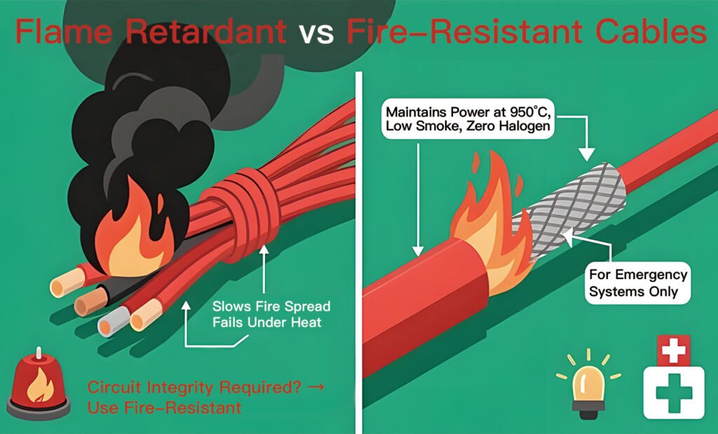
Core Distinction: Flame-Retardant vs. Fire-Resistant Cables
The primary structural distinction between flame-retardant and fire-resistant cables lies in their design objectives during a fire event. Flame-retardant cables are engineered to prevent the propagation of fire along the cable run; they self-extinguish once the external flame source is removed but will fail electrically if engulfed in fire. Fire-resistant cables are engineered to maintain circuit integrity and continue transmitting electrical power or signals for a specified duration (e.g., 90 or 120 minutes) while directly exposed to active flame. Structurally, fire-resistant cables incorporate specialized thermal barriers, such as mica glass tape, allowing them to survive extreme operational temperatures.
Technical Parameter & Structural Matrix
The following table outlines the material composition, regulatory standards, and operational parameters that differentiate these two safety-critical cable categories.
| Technical Parameter / Feature | Flame-Retardant Cables (e.g., FR-PVC / LSZH) | Fire-Resistant Cables (e.g., FR-Mica / Mineral Insulated) |
| Primary Safety Function | Retards fire spread; limits smoke/acid gas. | Maintains continuous electrical circuit integrity. |
| Key Structural Component | High-oxygen-index sheath; LSZH compounds. | Mica tape barrier over conductor; ceramicizing layer. |
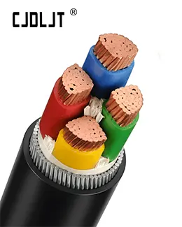
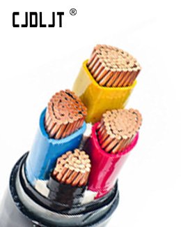
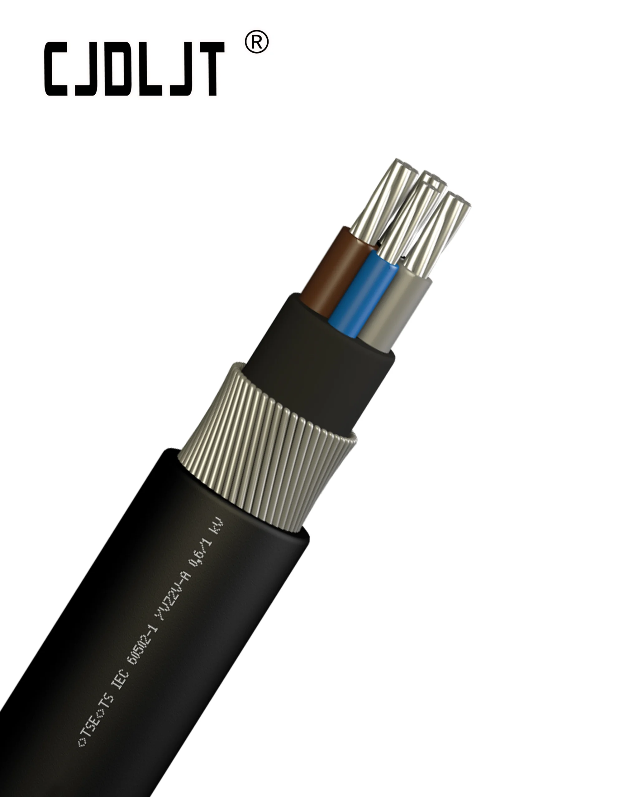
| Core Material Selection | Annealed Copper (or Al); PVC/XLPE with halogen additives. | Annealed Copper; Mica wrap + high-temp cross-linked insulation. |
| Standard Testing Protocol | IEC 60332-1 / IEC 60332-3 (Flame spread) | IEC 60331 (Circuit integrity under fire conditions) |
| Typical Test Parameters | Exposed to burner; flame vertical spread measured (<2.5m). | Exposed to 750°C – 950°C flame for 90–120 mins under rated voltage. |
| Primary Applications | General commercial buildings, data centers, staging areas. | Fire pumps, emergency lighting, smoke extraction fans. |
Structural Profile of Flame-Retardant Cables
Material Engineering
Flame-retardant cables rely entirely on the chemical composition of their jackets and insulation to suppress combustion.
- Halogenated Systems: Utilize PVC modified with additives like antimony trioxide. When exposed to fire, these release halogen gases that starve the flame of oxygen.
- LSZH Systems: Utilize aluminum trihydrate (ATH) or magnesium hydroxide fillers. Under fire conditions, these compounds undergo an endothermic decomposition, releasing water vapor to cool the cable and forming a protective char layer without emitting toxic halogens.
Operational Limits
During a fire, the structural integrity of the insulation degrades rapidly. While the outer jacket prevents the fire from traveling horizontally or vertically along a cable ladder, the interior polymer melts, leading to phase-to-phase short circuits.
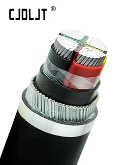
Structural Profile of Fire-Resistant Cables
The Mica Barrier Construction
The defining structural element of a fire-resistant cable is the inclusion of a high-temperature dielectric matrix directly over the raw Annealed Copper conductor. The most common execution involves wrapping the conductor with overlapping layers of Mica glass tape. Mica is a naturally occurring mineral with a melting point well above 1000°C.
Even when the primary outer insulation (XLPE or PVC) completely burns away into ash, the mica tape remains structurally intact, preventing the bare, energized conductors from physically touching each other or the grounded armor/tray, preserving circuit integrity.
Heavy-Duty Structural Variants (Mineral Insulated)
For ultra-critical environments, Mineral Insulated Copper Sheathed (MICS) cables are utilized. These eliminate organic polymers completely, utilizing bare copper rods embedded within a highly compressed magnesium oxide () powder insulation, all encased inside a seamless copper tube sheath. This structure can operate continuously at temperatures up to and survive short-term exposures exceeding 1000°C up to the melting point of copper itself (1083°C).