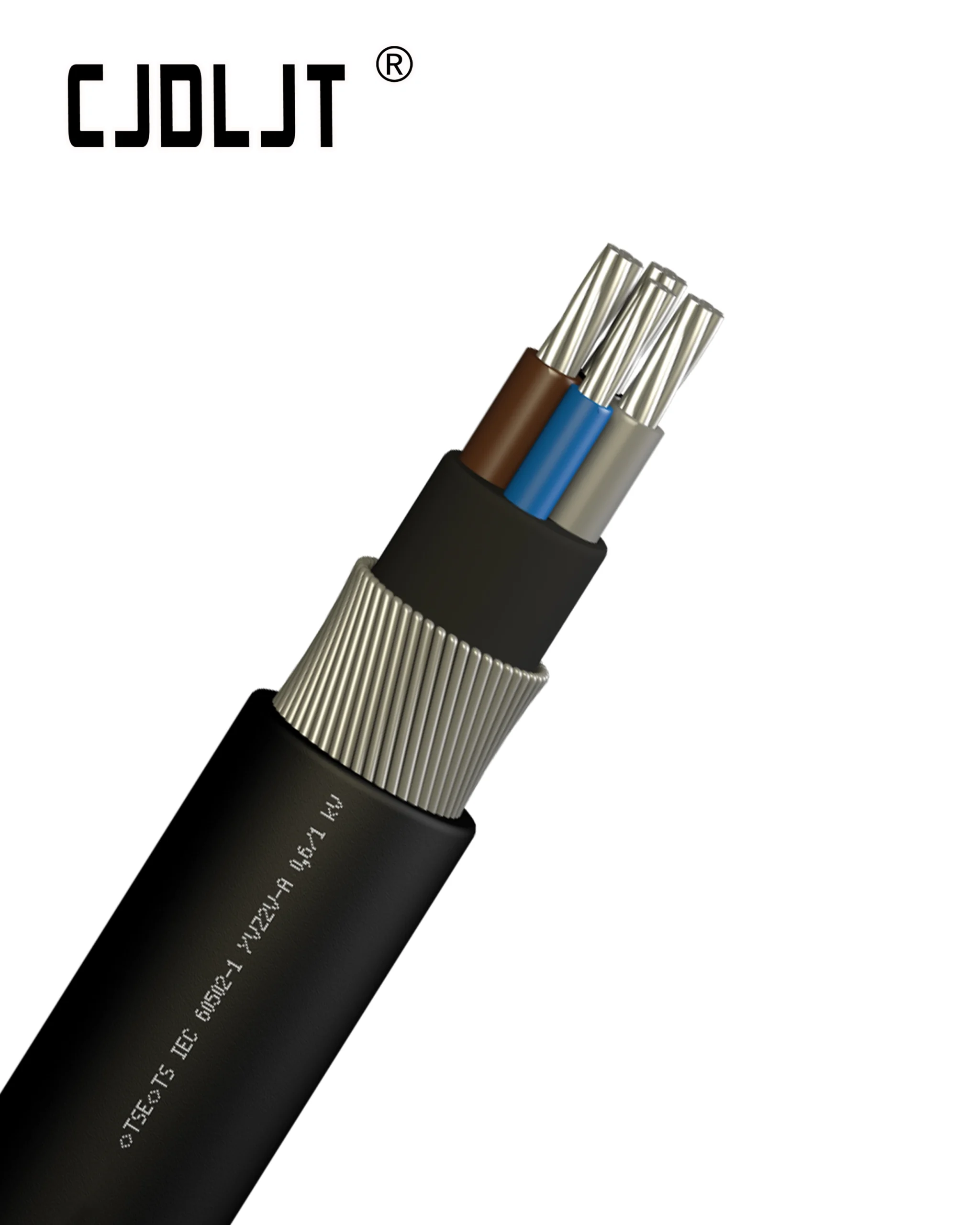


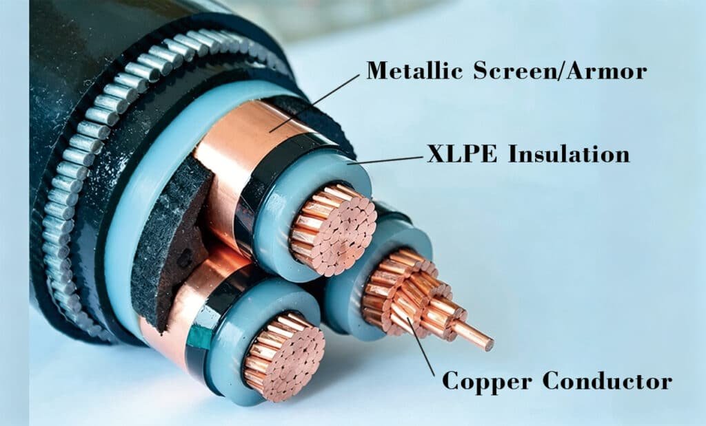
Partial Discharge (PD) is a localized dielectric breakdown that occurs within a small portion of a electrical cable’s insulation system under high-voltage stress. Unlike a complete breakdown, PD does not completely bridge the space between the primary Conductor and the outer ground shield/metallic Armor.
According to the international standard IEC 60270, PD occurs when the localized electric field intensity exceeds the dielectric strength of a specific weak point—such as an internal gas void, a micro-crack, or an impurity within the Cross-linked Polyethylene (XLPE) or PVC matrix. These micro-discharges emit transient electromagnetic pulses, acoustic waves, and chemical degradation byproducts that gradually erode the surrounding insulation over time.
Technical Parameter Matrix: PD Typologies and Characteristics
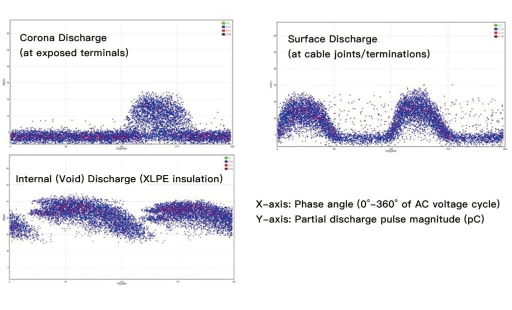
Partial discharge within power cables manifests in distinct forms depending on the physical nature and location of the insulation defect.
| PD Category | Primary Physical Origin | Typical Pulse Magnitude (pC) | Phase Resolved PD (PRPD) Pattern | Long-Term Operational Risk |
| Internal (Void) Discharge | Microscopic air/gas bubbles trapped inside the XLPE bulk. | 5 pC – 500 pC | Symmetric pulses centered in the 1st and 3rd quadrants (0° – 90° and 180° – 270°). | Critical: Triggers progressive electrical treeing leading to complete puncture. |
| Surface Discharge | Interfacial boundaries (e.g., cable joints, terminations, or stress cones). | 100 pC – 2000 pC | Asymmetric pulses clustered near the peaks of the AC voltage wave. | High: Leads to surface tracking, carbonization, and flashover. |
| Corona Discharge | Sharp metallic points or burrs exposed to air at exposed terminals. | 10 pC – 100 pC | Sharp, highly stable pulses concentrated tightly at the negative peak (270°). | Low to Moderate: Generates ozone; degrades external components over time. |
The Physics of PD Degradation and Failure
Dielectric Permittivity Mismatch
The primary driver of internal partial discharge is the stark difference in relative permittivity (εᵣ) between the solid insulation and the trapped gas void. For example, solid XLPE has a permittivity of approximately 2.3, while an air void has a permittivity of 1.0.
When an alternating current voltage is applied across the cable, the electric field strength (Evoid) inside the lower-permittivity air bubble is amplified relative to the surrounding solid medium:
E_void = εᵣ・E_insulation
Because air has a much lower breakdown threshold than XLPE (approx. 3 kV/mm vs.>20 kV/mm), the air within the void ionizes and discharges long before the rest of the insulation wall reaches its limit.
Electrical Treeing and Cable Failure Mechanisms
Each individual partial discharge event bombards the boundaries of the void with high-energy electrons and ultraviolet radiation, breaking the long-chain hydrocarbon polymers of the XLPE. This chemical decomposition produces volatile gases and deposits conductive carbon tracking paths along the micro-fissures.
Over months or years, these microscopic carbonized channels branch out through the insulation matrix in a structural pattern known as Electrical Treeing. As the conductive branches grow closer to the outer grounding screen, the remaining effective insulation thickness decreases until the system can no longer withstand the operating voltage, resulting in a disruptive short-circuit fault.