


Differences in Stranding Density Between Compacted and Non-Compacted Conductors
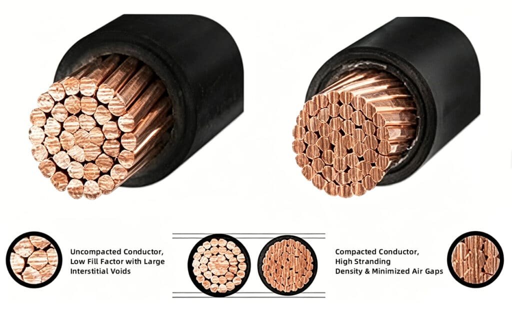
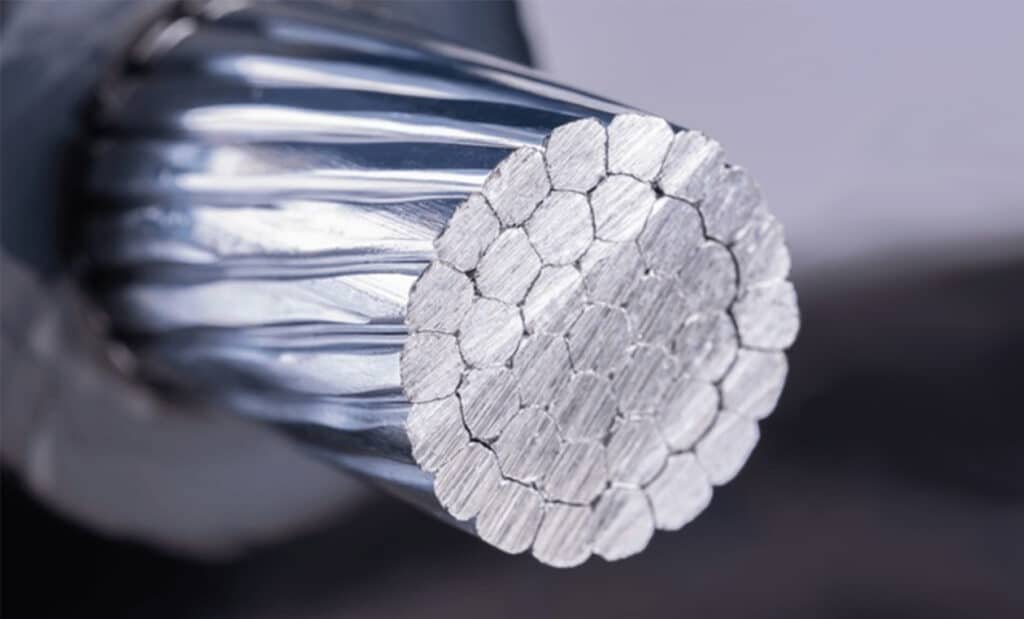
The primary difference between compacted and non-compacted conductors lies in the fill factor and the resulting outer diameter (OD). Non-compacted conductors retain standard helical interstitial voids between strands, yielding a fill factor of approximately 75% to 80%. Conversely, compacted conductors undergo drawing dies or rollers during the stranding process to deform individual wires, flattening the interstitial spaces. This increases the fill factor to 90%–95%, reducing the overall conductor OD by 6% to 10% while maintaining the identical cross-sectional area and DC resistance specified by IEC 60228 Class 2.
Technical Parameter Matrix: Compacted vs. Non-Compacted Conductors
The following structural data matrix contrasts the physical and electrical properties of concentric round non-compacted versus compacted copper/aluminum conductors.
| Technical Parameter | Non-Compacted Conductor | Compacted Conductor | Industrial Impact |
| Fill Factor (Approx.) | 75% – 80% | 90% – 95% | Higher density, less air entrapment. |
| Outer Diameter (OD) | Baseline (100%) | 90% – 94% of baseline | Smaller OD reduces material usage for subsequent layers. |
| Interstitial Voids | Significant air gaps present | Minimized/Flattened | Reduced longitudinal water ingress path. |
| Insulation Material Volume | Baseline requirement | Reduced by 5% – 12% | Lower consumption of XLPE or PVC. |
| Armor & Sheath Volume | Baseline requirement | Significantly reduced | Lowers overall cable weight and logistics costs. |
| Surface Smoothness | Rigid, corrugated profile | Smooth, uniform periphery | Reduces localized electrical field stress. |
| Contact Resistance | Standard | Lowered at terminations | Improved performance under mechanical compression. |
Engineering Impact on Cable Layer Architecture
Insulation Layer Optimization
Because a compacted conductor possesses a smoother, uniform outer periphery, it eliminates the high localized electrical field gradients (corona discharge risks) typical of the sharp ridges found on non-compacted strands. This smooth topography is highly beneficial for medium-voltage (MV) and high-voltage (HV) applications, allowing for a more stable interface with the inner semi-conductive shield.
Material Volumetric Efficiency
The reduction in conductor outer diameter creates a cascading material saving throughout the remaining cable architecture.
- XLPE/PVC Savings: A smaller conductor core requires less cross-sectional area of insulation compound to achieve the rated voltage wall thickness.
- Armor and Bedding: The inner bedding, metallic armor (e.g., SWA or AWA per BS 5467), and outer Flame Retardant or Low Smoke Zero Halogen (LSZH) sheathing dimensions scale down proportionally, reducing overall cable weight, maximizing conduit fill capacity, and lowering freight costs.