



Core Causes of Line Losses and Outages in Overhead Cable Selection
Selecting non-optimized or under-specified overhead conductors directly causes severe resistive power dissipation ($I^2R$ losses), structural thermal sag, and dielectric breakdown. Poor conductor sizing increases electrical resistance, accelerating thermal dissipation and voltage drops over long transmission distances. Substandard insulation materials fail to withstand continuous UV exposure, ambient temperature fluctuations, and environmental tracking, leading to phase-to-ground faults and frequent trip-outs. Furthermore, improper mechanical tensile design—such as ignoring local wind and ice load standards—causes excessive mechanical stress, line galloping, and structural fatigue failure. Aligning cable selection with rated system load, short-circuit requirements, and environmental stress profiles prevents structural and electrical grid failure.
Overhead Conductor Technical Parameter Matrix
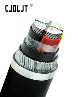
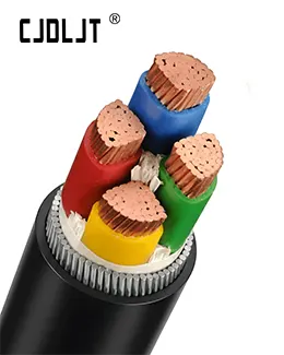
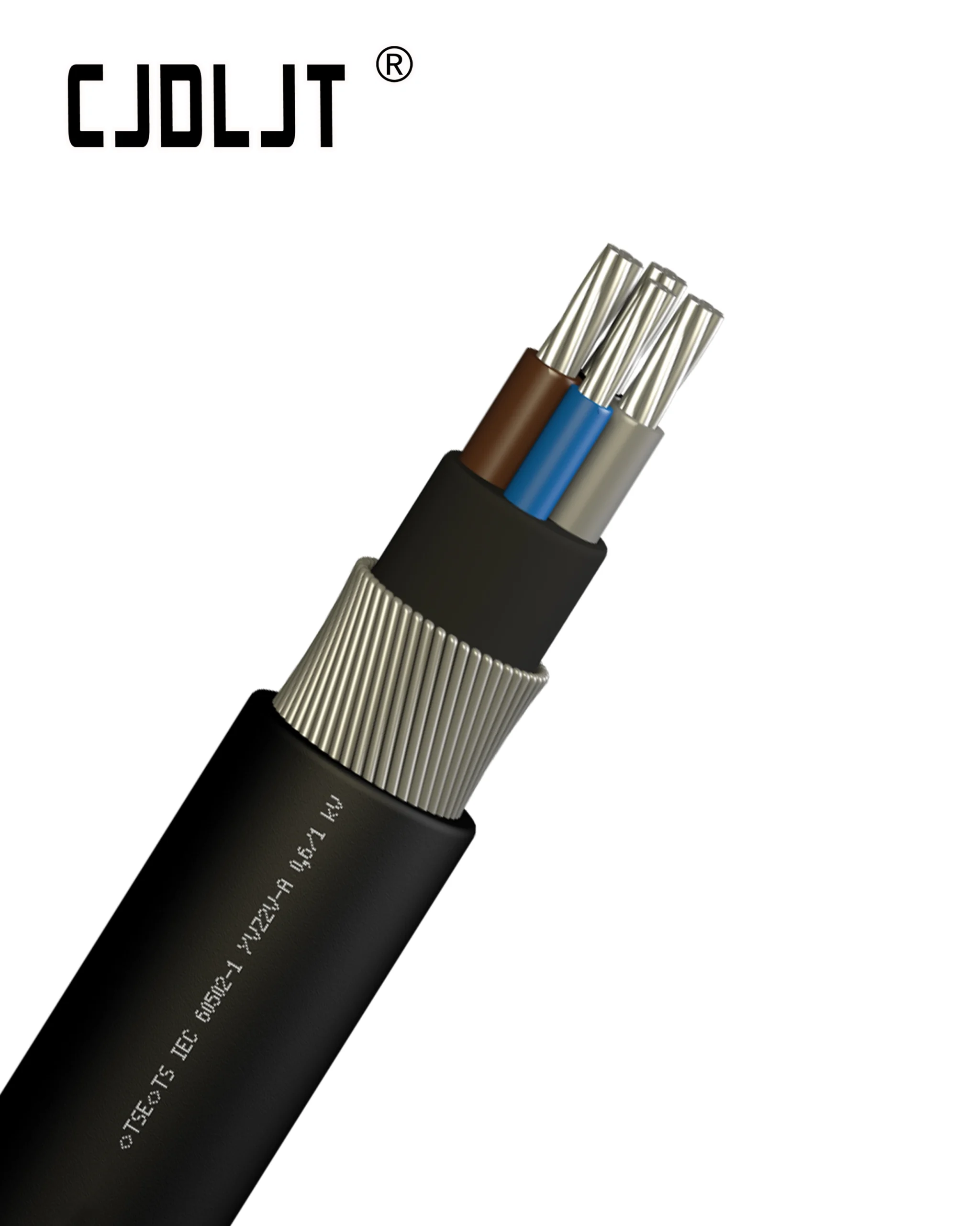
The structural selection of overhead conductors—whether bare, covered, or fully insulated aerial bundled cables (ABC)—determines system efficiency, current-carrying capacity, and fault resistance.
| Technical Parameter | All Aluminum Conductor (AAC) | All Aluminum Alloy Conductor (AAAC) | Aluminum Conductor Steel Reinforced (ACSR) | XLPE-Insulated Aerial Bundled Cable (ABC) |
| Applicable Standards | IEC 61089, BS 215 | IEC 61089, ASTM B399 | IEC 61089, ASTM B232 | IEC 60502-1, HD 626 |
| Conductor Material | EC-Grade Aluminum (1350) | Al-Mg-Si Alloy (6201-T81) | Aluminum (1350) / Galvanized Steel Core | Compacted Stranded Aluminum |
| Tensile Strength | Low (≈160–200 MPa) | High (≈295–325 MPa) | Very High (≈1000–1300 MPa steel core) | Medium (≈160–295 MPa) |
| Max Operating Temp. | 75 °C | 75 °C – 90 °C | 75 °C – 90 °C | 90 °C |
| Corrosion Resistance | Moderate | High (Marine/Industrial) | Moderate (Steel core susceptible without grease) | High (Fully Sheathed) |
| Outage Risk Profile | High sag under overload | Susceptible to vibration fatigue if dampening fails | High risk of phase clearance faults during wind | Minimal phase-to-phase short-circuit risks |
| Primary Voltage Range | Low Voltage (<1 kV) | Low to Medium Voltage (1–35 kV) | Medium to Extra-High Voltage (11–765 kV) | Low to Medium Voltage (0.6/1 kV – 35 kV) |
Technical Mechanisms Behind Cable-Induced Outages and Energy Losses
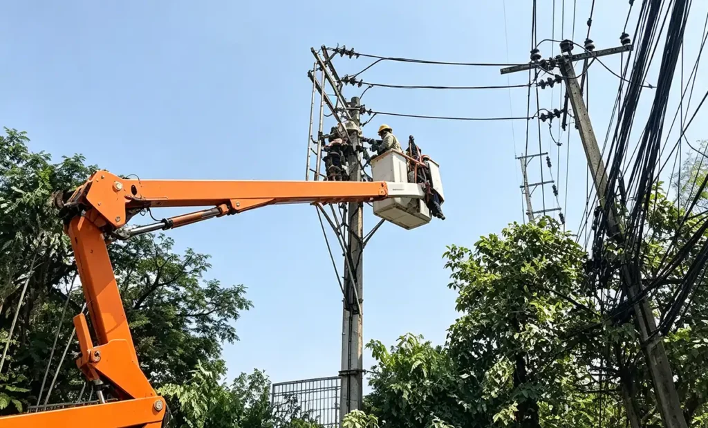
1. Conductor Cross-Section Under-Sizing and Thermal Loss
When an overhead line operates near or above its continuous ampacity rating, the electrical resistance (R) increases according to the conductor temperature coefficient of resistance (α):
Rₜ = R₂₀ [1 + α (T – 20)]
Under-sized conductors generate excessive heat, driving up internal resistance and multiplying total power loss (Pₗₒₛₛ = I² R). Excessive thermal buildup also accelerates the annealing of hard-drawn aluminum, permanently reducing its ultimate tensile strength (UTS) and causing irreversible line sag.
2. Dielectric Degradation in Covered and Insulated Overhead Lines
In Medium Voltage Aerial Bundled Cable (MV-ABC) systems, using substandard Polyvinyl Chloride (PVC) instead of Cross-linked Polyethylene (XLPE) or High-Density Polyethylene (HDPE) leads to premature dielectric rupture. Key breakdown factors include:
- UV Degradation: Solar radiation degrades un-stabilized polymer chains, generating micro-fissures in the insulation jacket.
- Electrical Tracking: Accumulation of surface pollution combined with moisture forms conductive paths, triggering flashovers across phase conductors or supporting hardware.
- Thermal Aging: Exceeding the max continuous conductor temperature (90 °C for XLPE vs. 70 °C for PVC) shortens insulation operational life according to the Arrhenius aging model.
3. Mechanical Stress Mismatch and Vibration Fatigue
Selecting low-tensile conductors (such as AAC) for long-span overhead configurations leads to line fatigue and mechanical failure:
- Aeolian Vibration: High-frequency, low-amplitude wind-induced vibrations cause bending stress concentration at suspension clamps, snapping individual outer conductor strands.
- Ice and Wind Loading: Insufficient mechanical safety factor (SF < 2.5 under peak local design loads according to NESC or IEC standards) causes physical breakage or dangerous phase-to-phase clashing during line galloping events.